

Top 10 Best Computer-Aided Design Software in India in 2027
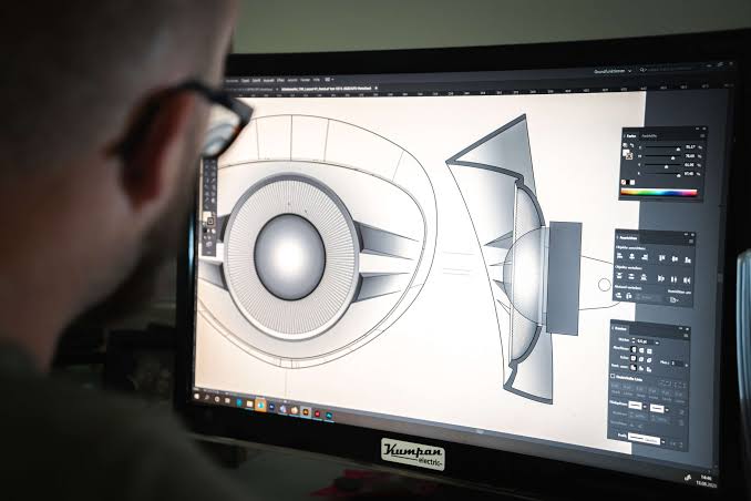
Computer-Aided Design (CAD) software has become an essential part of modern engineering, architecture, construction, manufacturing, automotive development, industrial product design and infrastructure planning. It enables professionals to create accurate two-dimensional technical drawings, develop sophisticated three-dimensional models, test product designs, prepare manufacturing specifications and improve collaboration between different engineering teams. From designing automobile components and industrial machinery to planning residential buildings, commercial complexes, electrical systems and large infrastructure projects, CAD software plays a central role in converting ideas into practical, technically detailed designs.
The growing adoption of digital engineering, smart manufacturing, Building Information Modelling (BIM), automation and product lifecycle management has expanded the applications of CAD software across Indian industries. Engineering companies increasingly require platforms that can support complex assemblies, parametric modelling, surface development, simulation, rendering, documentation and integration with Computer-Aided Manufacturing (CAM) systems. Architects and construction professionals, meanwhile, need tools that can coordinate building designs, structural information, mechanical, electrical and plumbing systems, and construction documentation.
The Indian market offers several established international CAD platforms, alongside affordable alternatives and open-source applications. The following software solutions provide capabilities across different design disciplines, ranging from conventional 2D drafting and architectural modelling to advanced mechanical engineering and industrial product development.
1. AutoCAD
AutoCAD, developed by Autodesk, is one of the most widely recognised Computer-Aided Design applications used by architects, civil engineers, mechanical engineers, electrical designers, interior designers and technical drafting professionals. The software has established a substantial presence in India’s architecture, engineering, construction and manufacturing industries because of its extensive drafting capabilities, flexible drawing environment and compatibility with commonly used engineering documentation formats. It supports both two-dimensional drafting and three-dimensional modelling, allowing professionals to create detailed technical drawings, layouts, plans, sections, elevations and engineering representations within a single environment.
One of AutoCAD’s most important capabilities is its precision-based drafting system. Users can create geometrical objects, lines, polylines, circles, arcs, dimensions, annotations, hatches and construction elements with accurate measurements. Its coordinate-based drawing environment allows designers to work with specific dimensions and technical standards rather than relying entirely on visual approximation. Tools such as object snaps, polar tracking, dynamic input, layers and reusable blocks make it easier to prepare detailed drawings while maintaining consistency throughout a project. These capabilities are particularly useful for Indian architectural practices, civil engineering consultancies, infrastructure contractors and manufacturing organisations that regularly exchange technical drawings.
AutoCAD also provides extensive layer-management functionality. Designers can organise drawing components according to their purpose, discipline, material, visibility or construction stage. For example, an architectural drawing can maintain separate layers for walls, doors, windows, electrical layouts, plumbing networks, dimensions and annotations. This arrangement makes large technical drawings easier to manage and revise. Block creation and reusable drawing elements further improve productivity, especially when professionals repeatedly use standard symbols, equipment representations, furniture layouts or engineering components.
Its three-dimensional modelling capabilities allow users to create solid, surface and mesh-based representations. Although AutoCAD is not a substitute for specialised parametric mechanical design platforms, its 3D tools are useful for conceptual modelling, visualisation and representing physical components. The software also supports external references, drawing comparison, data extraction and customisation through scripts, APIs and specialised toolsets. These capabilities allow organisations to standardise drafting procedures and automate repetitive tasks.
AutoCAD’s specialised toolsets extend its usefulness across different professional disciplines. Depending on the subscription and product configuration, users can access additional capabilities for architecture, mechanical design, electrical engineering, map production and plant-related documentation. AutoCAD Architecture, AutoCAD Mechanical and AutoCAD Electrical provide discipline-oriented features that help professionals work with specialised drawing requirements.
The platform also supports collaboration through cloud-connected workflows, web access and mobile access, allowing authorised users to view, edit or share drawings across different devices. DWG and DXF compatibility makes it particularly relevant for organisations that exchange drawings with contractors, consultants, suppliers and customers using different CAD applications. For Indian professionals seeking a widely recognised drafting platform with extensive industry adoption, AutoCAD remains an important option.
2. SOLIDWORKS
SOLIDWORKS, developed by Dassault Systèmes, is a widely used three-dimensional CAD platform designed primarily for mechanical engineering, industrial product development, machine design and manufacturing. It is particularly relevant to Indian automotive component manufacturers, industrial machinery companies, engineering consultancies, product development businesses and organisations involved in designing mechanical assemblies. The software provides a parametric modelling environment in which designers can develop individual components, combine them into assemblies and generate detailed engineering drawings for manufacturing.
One of the major strengths of SOLIDWORKS is its feature-based parametric modelling capability. Designers can create components using sketches, extrusions, revolutions, sweeps, lofts, fillets, chamfers, holes and other modelling operations. Each operation is recorded in a feature tree, allowing users to modify earlier design decisions without rebuilding the entire model. This approach is particularly useful when developing products that require repeated modifications, dimensional adjustments or design variations. Engineers can change a component’s dimensions and constraints while allowing the associated features and assemblies to update accordingly.
The software offers comprehensive assembly modelling capabilities. Engineers can bring multiple components together, establish mechanical relationships, define movement constraints and evaluate how different parts interact. This is important for designing industrial machinery, automotive assemblies, manufacturing equipment, pumps, valves, consumer products and mechanical systems. Interference detection and clearance evaluation help identify potential clashes between components before manufacturing begins. The ability to examine complex assemblies also helps engineering teams understand how individual parts fit into a complete product.
SOLIDWORKS provides sheet metal design tools that support the development of enclosures, brackets, panels, cabinets and fabricated metal components. Users can create bends, flanges, hems, corner treatments and flat patterns while accounting for manufacturing requirements. Its weldment functionality supports the design of structural frames, fabricated assemblies and welded components. These features make the platform relevant to Indian fabrication businesses, industrial equipment manufacturers and companies producing customised machinery.
Another important capability is its engineering drawing environment. SOLIDWORKS can generate two-dimensional manufacturing drawings from three-dimensional models, including dimensions, sections, auxiliary views, annotations, bills of materials and other technical information. When the underlying model changes, associated drawing views can update, reducing the possibility of inconsistencies between design models and manufacturing documentation.
The software also offers simulation and analysis capabilities through its associated engineering products and modules. Depending on the selected package, users can evaluate structural behaviour, displacement, stress, thermal conditions, motion and other engineering parameters. SOLIDWORKS Simulation helps engineers examine how components may respond to different loading conditions, while motion analysis supports the evaluation of moving assemblies. These tools can reduce dependence on repeated physical prototypes during early product development.
SOLIDWORKS further supports manufacturing workflows through its CAM-related capabilities and integration with product data management solutions. Organisations can manage design revisions, control access to engineering documents and maintain product development records. Its ecosystem also includes visualisation, electrical design and specialised engineering applications. The availability of training programmes, educational resources and professional expertise makes it a familiar platform among engineering institutions and industrial users in India.
For businesses developing mechanical products that require accurate modelling, assembly management, manufacturing drawings and engineering validation, SOLIDWORKS provides a comprehensive design environment.
3. Autodesk Fusion
Autodesk Fusion is an integrated cloud-connected product development platform that combines computer-aided design, computer-aided manufacturing, computer-aided engineering and electronics design capabilities. It is particularly useful for startups, product designers, small and medium-sized manufacturing businesses, engineering teams, industrial designers and professionals developing physical products. Its combination of modelling, simulation, machining and collaborative design tools makes it suitable for organisations that want to manage several stages of product development within a connected environment.
One of Fusion’s most important capabilities is its integrated 3D modelling environment. It supports parametric, direct, surface, freeform and mesh-based modelling approaches, giving designers flexibility when developing different types of products. Parametric modelling allows users to create designs through editable dimensions and feature histories, while direct modelling provides greater freedom to modify existing geometry. Surface modelling is useful for developing complex external shapes, while freeform tools support organic and ergonomic designs for consumer products, equipment housings and industrial components.
Fusion also offers extensive assembly and component management capabilities. Designers can organise individual components, establish relationships between parts and examine how a complete product is assembled. This is useful for developing mechanical devices, electronic enclosures, furniture components, industrial equipment and consumer products. The platform allows design teams to work with different modelling approaches without necessarily moving between multiple independent applications.
Its manufacturing capabilities are another significant advantage. Fusion includes integrated CAM tools for preparing machining operations and generating toolpaths for computer-controlled manufacturing equipment. Depending on the available licence and modules, users can work with milling, turning, cutting and other manufacturing processes. This integration helps reduce the gap between product design and production preparation. Engineers can develop a model and subsequently use the same design environment to prepare machining strategies, examine toolpaths and generate manufacturing instructions.
The platform also includes simulation capabilities that help designers evaluate product performance during development. Depending on the subscription, available tools can support structural analysis, thermal evaluation, modal analysis and other engineering studies. These capabilities are useful when assessing whether a component can withstand expected operating conditions or whether a design requires modifications before manufacturing.
Fusion’s electronics design functionality makes it particularly interesting for businesses developing products that combine mechanical and electrical components. Users can work with printed circuit board designs, electronic schematics and associated mechanical representations. The ability to coordinate electronic and mechanical design information is valuable for developing connected devices, industrial controllers, embedded systems and consumer electronics.
Cloud-connected collaboration is another important feature. Design information can be stored and shared through Autodesk’s connected environment, allowing authorised team members to access project data and review design changes. Version management and collaborative workflows help reduce confusion when multiple professionals contribute to the same product development project. However, organisations should evaluate internet connectivity, cloud storage requirements and data-management policies before adopting a cloud-connected workflow.
Fusion is also relevant to India’s growing startup and prototyping ecosystem. Product development companies can use it to design components, prepare 3D-printable models, develop CNC machining instructions and manage engineering revisions. Its combination of CAD, CAM, CAE and electronics tools makes it a versatile option for organisations that need an integrated product development platform without adopting several separate applications.
4. CATIA
CATIA, developed by Dassault Systèmes, is an advanced computer-aided design and product engineering platform widely used in automotive, aerospace, industrial equipment, transportation and complex manufacturing environments. It is particularly suited to organisations that need sophisticated surface modelling, large assembly management, complex product development and multidisciplinary engineering collaboration. In India, CATIA is relevant to automotive manufacturers, aerospace engineering organisations, automotive component suppliers, industrial design companies and engineering service providers working with international manufacturing standards.
One of CATIA’s most recognised capabilities is its advanced surface modelling environment. Designers can create complex geometries, smooth external surfaces and sophisticated product shapes that may be difficult to develop using conventional solid-modelling tools alone. This makes the platform particularly useful in automotive body design, aircraft structures, vehicle interiors, aerodynamic components and consumer product development. Engineers can work with curves, surfaces, transitions and continuity conditions to develop geometries that satisfy both functional and aesthetic requirements.
CATIA also provides powerful parametric and feature-based modelling capabilities. Designers can construct complex three-dimensional components using sketches, solids, surfaces, geometric constraints and engineering features. Relationships between design elements can be maintained through associative modelling, allowing changes to one part of a design to influence connected components. This becomes important when developing products with numerous interconnected elements and complicated design dependencies.
Its assembly design environment supports the development of large and sophisticated products. Automotive and aerospace projects can involve thousands of individual components, each with its own dimensions, specifications and manufacturing requirements. CATIA provides tools for managing these assemblies, positioning components, examining relationships and coordinating design information. Engineers can assess how different components fit together and identify potential design conflicts during the development process.
CATIA is also designed to support multidisciplinary engineering. Its capabilities extend beyond conventional mechanical modelling into areas such as electrical systems, composite materials, engineering analysis, manufacturing preparation and product development. Organisations can coordinate information across different technical disciplines rather than maintaining isolated design environments. This is particularly valuable for aerospace and automotive projects, where mechanical, electrical, structural and manufacturing teams must work with interconnected product information.
Another important aspect is its relationship with the 3DEXPERIENCE platform. This environment provides broader product lifecycle management and collaboration capabilities, allowing organisations to manage engineering data, product configurations, design revisions and workflows. Teams can coordinate design activities across different locations and departments while maintaining greater control over product information. The exact capabilities available depend on the selected CATIA configuration and platform licensing.
CATIA is particularly useful for complex automotive engineering applications, including vehicle body structures, chassis components, interior systems, engine-related components and exterior styling. In aerospace, it supports the development of aircraft structures, aerodynamic surfaces, interior assemblies and other specialised components. Its sophisticated modelling environment also makes it relevant to industrial machinery and transportation engineering.
Because CATIA is a comprehensive professional engineering platform, it generally requires specialised training and an investment in implementation, infrastructure and licensing. However, for organisations involved in complex product engineering, advanced surface development and multidisciplinary manufacturing projects, it offers a highly capable design environment.
5. Siemens NX
Siemens NX is an advanced computer-aided design, manufacturing and engineering platform developed by Siemens Digital Industries Software. It is designed for organisations involved in complex product development, precision manufacturing, industrial machinery, automotive engineering, aerospace and high-value component production. The software combines sophisticated 3D modelling, assembly design, simulation and manufacturing preparation capabilities, making it relevant to large engineering organisations as well as specialised manufacturing businesses in India.
One of Siemens NX’s major strengths is its comprehensive modelling environment. It supports parametric, direct, synchronous and surface-based modelling approaches. Engineers can develop components using feature-based techniques or modify existing geometry directly, depending on the design requirements. Synchronous technology is particularly useful when working with imported or legacy models because it allows users to make changes without depending entirely on the original feature history. This flexibility helps organisations manage designs received from different suppliers and engineering partners.
NX provides advanced assembly design capabilities for managing complicated products containing numerous components. Engineers can organise assemblies, examine component relationships, evaluate clearances and coordinate design changes. This is important for automotive, aerospace and industrial equipment manufacturers, where a single product may contain hundreds or thousands of interconnected parts. Its assembly tools help engineering teams maintain consistency across product configurations and improve the management of complex design structures.
The platform also includes powerful surface modelling capabilities. Designers can develop intricate shapes, transitions and complex geometries for industrial products, vehicle components and specialised equipment. Its modelling tools support both functional engineering requirements and the development of sophisticated product forms. Engineers can combine solid and surface modelling methods to produce designs that meet dimensional, structural and manufacturing requirements.
Manufacturing integration is one of Siemens NX’s important advantages. NX CAM supports computer-aided manufacturing workflows, including the preparation of machining operations and toolpaths for CNC equipment. Its capabilities cover different manufacturing processes, including milling, turning and other specialised operations, depending on the configuration. By integrating design and manufacturing information, NX can help reduce programming errors and improve coordination between product engineering and production departments.
NX also offers simulation and engineering analysis capabilities. Through its integrated engineering environment and associated Siemens simulation products, organisations can evaluate structural behaviour, thermal performance, motion, fluid-related conditions and other engineering characteristics. These tools help designers examine potential product performance issues before physical production. Simulation can also support design optimisation by helping engineers understand how changes in geometry, materials or operating conditions affect the final product.
Another significant capability is its integration with the broader Siemens digital manufacturing ecosystem. NX can work alongside product lifecycle management, manufacturing execution and simulation solutions. This allows organisations to connect product design with production planning, manufacturing engineering and operational processes. For large manufacturing businesses, this integration can provide a more connected digital engineering environment.
In India, Siemens NX is relevant to automotive OEMs, component manufacturers, industrial machinery producers, aerospace suppliers, precision engineering businesses and companies operating sophisticated CNC manufacturing facilities. It is particularly appropriate for organisations that require a combination of advanced CAD, CAM and CAE capabilities within a connected engineering platform.
6. PTC Creo
PTC Creo is a professional 3D computer-aided design platform developed by PTC for product engineering, mechanical design, industrial equipment development and manufacturing. It is widely associated with parametric modelling and advanced engineering workflows, making it suitable for organisations that develop complex mechanical products and require detailed control over product geometry, dimensions, assemblies and manufacturing documentation. In India, the software is relevant to automotive component manufacturers, industrial machinery businesses, engineering design consultancies, aerospace suppliers and companies involved in precision product development.
One of Creo’s central capabilities is its parametric modelling environment. Engineers can create three-dimensional components using sketches, dimensions, constraints and feature-based operations. Each modelling operation contributes to a structured design history, allowing users to modify dimensions and engineering features while maintaining relationships between different elements. This approach is particularly valuable when developing products that undergo frequent engineering changes or require multiple design configurations.
Creo supports solid modelling, surface modelling and direct modelling workflows. Its advanced surface capabilities help designers create complicated product geometries, while its solid modelling tools are suitable for developing mechanical components, industrial equipment and manufactured products. The combination allows engineers to work on both the functional and aesthetic aspects of product development. Its direct modelling functionality also helps users make modifications to existing geometries, including imported models, without always needing access to their original design history.
The software provides extensive assembly design capabilities. Engineers can combine individual components into larger product assemblies, define mechanical relationships and examine how parts interact. Large assembly management tools help users work with complicated product structures while maintaining control over individual components. This is particularly useful for machinery manufacturers, automotive engineering companies and businesses developing products with numerous interconnected parts. Assembly analysis can also help identify interference and potential fitting problems before the manufacturing stage.
Creo’s sheet metal design capabilities are useful for designing enclosures, panels, brackets, cabinets and other fabricated components. Engineers can create sheet metal features, define bends and generate flat patterns for manufacturing. The software also provides specialised tools for designing piping, cabling and other engineering systems, depending on the selected configuration. These capabilities are relevant to industrial equipment manufacturers and organisations developing products that involve complicated mechanical and electrical arrangements.
Another important feature is Creo’s simulation and analysis ecosystem. Creo Simulation Live and other associated engineering capabilities support different forms of product evaluation. Engineers can examine structural performance, thermal behaviour and other design parameters to identify potential weaknesses. Generative design capabilities can also help explore alternative geometries based on defined engineering requirements and constraints. These features are useful for organisations seeking to reduce material consumption, improve product performance and evaluate different design possibilities.
Creo also supports manufacturing-oriented workflows. Its associated manufacturing capabilities help engineering teams prepare machining strategies and coordinate design information with production requirements. Integration with PTC’s product lifecycle management environment enables businesses to manage engineering revisions, product configurations, technical documentation and design-related workflows.
A particularly relevant aspect of Creo is its usefulness in organisations where engineering accuracy and design control are important. Changes to one component can affect multiple related components, making structured design management essential. The platform’s parametric and associative capabilities help teams maintain relationships across product models and documentation.
For Indian manufacturers and engineering organisations involved in sophisticated mechanical product development, Creo provides an extensive environment for modelling, assembly management, engineering analysis and manufacturing preparation.
7. Autodesk Revit
Autodesk Revit is a Building Information Modelling software platform designed for architecture, structural engineering and building services design. Unlike conventional drafting applications that primarily represent buildings through separate lines and geometric drawings, Revit allows professionals to develop intelligent three-dimensional building models containing associated information about architectural elements, materials, dimensions and building systems. It is widely used by architecture firms, construction companies, structural consultants, engineering service providers and infrastructure-related organisations.
One of Revit’s most important capabilities is its object-based modelling environment. Walls, doors, windows, floors, roofs, columns, beams and other building elements are represented as intelligent objects rather than ordinary drawing lines. Each object can contain information about its dimensions, materials, properties and relationships with other building components. This approach helps architects and engineers create coordinated building models while maintaining consistency across different project views.
Revit supports architectural design and documentation through a unified modelling environment. Architects can develop floor plans, elevations, sections, schedules and three-dimensional views from the same building model. When a design change is made, the associated views can update automatically, reducing the need to modify multiple drawings independently. For example, changing the location of a wall can be reflected in the relevant floor plan, elevation and section views.
Its structural engineering capabilities allow professionals to model structural elements such as beams, columns, foundations, floors and reinforcement-related components. Structural consultants can coordinate their models with architectural designs and prepare detailed structural documentation. The software also supports analytical modelling workflows that can be used alongside specialised structural analysis applications.
Revit’s mechanical, electrical and plumbing capabilities make it particularly useful for multidisciplinary building projects. Engineers can model heating, ventilation and air-conditioning systems, electrical circuits, lighting layouts, plumbing networks, drainage arrangements and other building services. These systems can be coordinated with architectural and structural elements, helping identify spatial conflicts before construction. This is especially valuable in commercial buildings, hospitals, airports, hotels, industrial facilities and large residential developments.
Another major advantage is its clash detection and coordination ecosystem. Through collaboration with other Autodesk applications and coordination tools, project teams can identify conflicts between architectural, structural and building services models. For example, a ventilation duct passing through a structural beam or a plumbing pipe interfering with an electrical installation can be identified during the design coordination process. Resolving such conflicts before construction can help reduce rework, delays and additional project costs.
Revit also provides scheduling and quantity-related functionality. Users can generate schedules for doors, windows, materials, structural components and other building elements. This information can support documentation, project estimation and construction planning. The software also supports visualisation and rendering workflows, enabling architects to communicate building designs through realistic representations.
Cloud-connected collaboration through Autodesk Construction Cloud and related services can help distributed project teams coordinate their work. Multiple professionals can contribute to different project disciplines while maintaining access to shared building information, subject to the relevant licensing and collaboration arrangements.
For Indian architecture and construction firms working on increasingly complex residential, commercial, institutional and infrastructure-related buildings, Revit offers a comprehensive BIM environment that connects design development with documentation and multidisciplinary coordination.
8. SketchUp
SketchUp, developed by Trimble, is a three-dimensional modelling application widely used in architecture, interior design, landscape design, furniture development and conceptual product visualisation. It is particularly popular among professionals who require an accessible modelling environment for quickly converting design concepts into three-dimensional representations. In India, the software is relevant to architects, interior designers, furniture manufacturers, residential design consultants, real estate visualisation businesses and independent design professionals.
One of SketchUp’s most recognised features is its comparatively accessible modelling interface. Users can create and modify three-dimensional forms using drawing, pushing, pulling, moving, rotating and other direct modelling operations. Its Push/Pull functionality allows a two-dimensional surface to be transformed into a three-dimensional object by extending or recessing its geometry. This makes it possible to develop basic building forms, furniture components, interior layouts and product concepts without requiring extensive parametric modelling knowledge.
The software is especially useful during the conceptual design stage. Architects can quickly develop building massing models, examine different spatial arrangements and communicate proposed designs to clients. Interior designers can represent rooms, furniture arrangements, wall treatments, ceilings, lighting concepts and decorative elements. The ability to visualise spaces in three dimensions makes it easier for clients to understand proposed designs before implementation.
SketchUp’s component and group functionality helps users organise complicated models. Repeated elements such as windows, doors, furniture, lighting fixtures and architectural details can be represented as reusable components. Changes to component instances can be managed more efficiently, reducing repetitive modelling work. Groups also help prevent unrelated geometry from becoming unintentionally connected during modelling.
One of the platform’s major advantages is its extensive 3D Warehouse library. Designers can access a large collection of ready-made models, including furniture, building components, equipment, appliances and other objects. This can accelerate the development of architectural and interior visualisations. Professionals can also create and upload their own models for repeated use. However, imported components should be checked for dimensional accuracy, geometry quality and suitability for the intended project.
SketchUp supports the development of detailed architectural models through its broader ecosystem. LayOut can be used to prepare two-dimensional presentation documents and construction-related drawing sheets from SketchUp models. Different rendering extensions can produce more realistic representations of materials, lighting, textures and environmental conditions. This allows designers to create client presentations and visual proposals without necessarily moving to an entirely separate modelling application.
The software is also useful for landscape and outdoor design. Professionals can represent gardens, pathways, outdoor furniture, terrain elements and building surroundings. For real estate developers and design consultants, this can help communicate the appearance and spatial organisation of proposed developments.
However, SketchUp should be distinguished from specialist engineering platforms such as SOLIDWORKS, CATIA and Siemens NX. Its primary strength is accessible conceptual and architectural modelling rather than sophisticated mechanical parametric engineering, complex manufacturing assemblies or advanced engineering simulation. Professionals working on technically demanding products may need additional software for detailed engineering validation.
For Indian architects, interior designers, furniture businesses and design consultants seeking a flexible three-dimensional modelling platform, SketchUp offers an approachable environment for developing and presenting design concepts.
9. Bentley MicroStation
Bentley MicroStation is a computer-aided design and engineering software platform developed by Bentley Systems. It is primarily used for infrastructure design, civil engineering, transportation projects, utilities, industrial facilities and large-scale engineering documentation. The platform is particularly relevant to organisations involved in roads, railways, bridges, airports, water infrastructure, urban development and public infrastructure projects.
One of MicroStation’s major capabilities is its precision-based drafting and modelling environment. Engineers can create detailed two-dimensional drawings and three-dimensional models using accurate geometric construction tools. Its design environment supports the preparation of engineering layouts, technical plans, sections, elevations and complex infrastructure representations. This makes it useful for engineering consultants and contractors working on projects that involve large quantities of interconnected technical information.
The software provides extensive support for working with different design data formats. This is important in infrastructure projects because engineering information may originate from multiple consultants, contractors, survey teams and specialist design applications. MicroStation supports DGN as its native design format and can work with other commonly used engineering file formats. Its interoperability capabilities help organisations coordinate information across different project participants.
MicroStation also offers advanced reference and design management functionality. Engineers can attach external design files, coordinate different drawing components and manage project information across multiple documents. This becomes particularly useful when preparing large infrastructure drawings involving roads, utilities, structures, drainage networks and other engineering elements.
Its three-dimensional modelling capabilities support the development of infrastructure-related geometry and engineering representations. Designers can work with solid and surface modelling tools to represent structures, components and spatial arrangements. The platform can also be used alongside specialised Bentley applications for civil engineering, structural design, road and rail infrastructure and other technical disciplines.
Bentley’s broader infrastructure software ecosystem is an important part of its appeal. Applications such as OpenRoads, OpenRail, OpenBridge and OpenBuildings provide specialised capabilities for different engineering disciplines. These solutions can work with MicroStation-based design environments to support more comprehensive project workflows. For example, road engineering teams can develop corridor models, railway consultants can coordinate track-related designs, and structural engineers can work on bridge and building components using specialised applications.
Another important feature is its suitability for large infrastructure data environments. Projects involving highways, rail networks, industrial facilities and urban utilities often require the coordination of information from several technical disciplines. Bentley’s connected project and infrastructure data solutions can help teams manage engineering information throughout different stages of a project.
In India, MicroStation and Bentley’s broader software ecosystem are relevant to infrastructure consultants, engineering contractors, transportation authorities, public infrastructure organisations and companies involved in large-scale construction projects. Its applications are particularly valuable where accurate engineering documentation, infrastructure modelling and multidisciplinary coordination are essential.
For organisations working on complex infrastructure developments rather than conventional consumer product design, MicroStation provides a specialised CAD environment with capabilities suited to large engineering projects.
10. FreeCAD
FreeCAD is an open-source parametric three-dimensional computer-aided design application designed for mechanical engineering, product development, architecture, technical modelling and educational applications. Unlike many commercial CAD platforms that require paid subscriptions or enterprise licensing arrangements, FreeCAD provides users with access to its core modelling capabilities without a conventional software licence fee. This makes it particularly relevant to engineering students, independent designers, startups, small manufacturing businesses, researchers and professionals looking for an affordable alternative to proprietary CAD applications.
One of FreeCAD’s most important capabilities is its parametric modelling environment. Users can create three-dimensional objects through sketches, geometrical constraints, dimensions and feature-based operations. The software maintains a design history that allows users to revisit and modify earlier modelling operations. For example, a designer developing a mechanical bracket can modify its dimensions, change the position of holes or adjust its thickness without necessarily recreating the entire model. This approach makes FreeCAD useful for projects that involve repeated design modifications and dimensional experimentation.
The application is organised around different workbenches, each providing tools for specific design activities. The Part Design workbench supports the creation of solid mechanical components through operations such as extrusion, revolution, pocketing and other feature-based modelling techniques. The Sketcher workbench allows users to create two-dimensional profiles and apply geometrical and dimensional constraints. The Part workbench provides additional solid modelling operations, while the Draft workbench offers tools for technical drafting and geometrical construction.
FreeCAD also provides surface and mesh-related functionality. Users can work with different geometric representations and import or export models through supported file formats. This is useful when collaborating with professionals who use commercial CAD applications or when preparing designs for prototyping and manufacturing. Its compatibility with commonly used formats such as STEP, IGES, STL and DXF helps facilitate the movement of design information between different engineering environments, although individual format support and the quality of imported geometry should be checked for specific workflows.
The software includes an assembly-oriented ecosystem that can support the development of products containing multiple components. Depending on the installed version and available workbenches, users can organise components, establish assembly relationships and examine how different parts fit together. This is relevant to students and smaller engineering teams developing mechanical devices, equipment prototypes and product concepts.
FreeCAD’s BIM-related functionality makes it useful for certain architectural and building design workflows. The BIM workbench provides tools for representing architectural elements and developing building-related models. Users can create walls, structural elements and other building components while working with associated geometric and information-based properties. However, organisations requiring extensive enterprise-level BIM coordination and specialised construction documentation may find dedicated applications such as Autodesk Revit or Graphisoft Archicad more suitable.
Another important advantage is the software’s customisation and extensibility. FreeCAD supports Python-based scripting, allowing technically experienced users to automate modelling operations, create customised workflows and extend the application’s capabilities. Its modular architecture and community-developed workbenches provide additional functionality for specialised applications. This flexibility makes it useful for educational institutions, engineering researchers and developers interested in experimenting with CAD automation.
FreeCAD also supports workflows associated with 3D printing. Users can develop three-dimensional models, prepare suitable mesh representations and export designs for use with compatible slicing applications. This makes it valuable for rapid prototyping, product experimentation, educational projects and small-scale manufacturing activities.
Since FreeCAD is an open-source application, users should understand that its support model differs from commercial enterprise software. Organisations may need to depend on community documentation, forums, external training providers or internal technical expertise for troubleshooting and implementation. Some advanced workflows may also require additional extensions or applications.
For Indian engineering students, independent product designers, small businesses and manufacturing startups, FreeCAD offers an accessible entry point into parametric computer-aided design. Its combination of modelling tools, technical drafting, customisation and open-source accessibility makes it a useful alternative for users who want to develop engineering design capabilities without committing to expensive commercial software subscriptions.
Conclusion
Computer-Aided Design software has become an important component of India’s engineering, architecture, manufacturing and infrastructure industries. The ten platforms discussed above provide different capabilities for professionals working across these sectors. AutoCAD remains a widely recognised option for technical drafting and general-purpose design, while SOLIDWORKS, CATIA, Siemens NX and PTC Creo provide specialised environments for mechanical engineering, industrial product development and manufacturing. Autodesk Fusion offers an integrated approach to CAD, CAM, CAE and electronics design, making it useful for product development businesses and smaller engineering teams.
For architecture and construction, Autodesk Revit provides a comprehensive Building Information Modelling environment, while SketchUp offers accessible three-dimensional modelling capabilities for conceptual architecture and interior design. Bentley MicroStation addresses the requirements of infrastructure engineering and large-scale technical design projects. FreeCAD provides an open-source alternative for users seeking parametric modelling and technical design capabilities without conventional commercial licensing costs.
The choice of CAD software ultimately depends on the nature of the work, the complexity of the designs, the size of the organisation, the required engineering capabilities and the available budget. Businesses should also consider compatibility with existing software, file exchange requirements, licensing arrangements, training availability, technical support and integration with manufacturing or project management systems.
For organisations involved in product engineering, the ability to combine accurate modelling with simulation, assembly management and manufacturing preparation can be particularly important. Architecture and construction businesses may place greater emphasis on BIM, drawing coordination, project documentation and multidisciplinary collaboration. Similarly, educational institutions and independent designers may prioritise accessibility, learning resources and affordability.
As Indian businesses increasingly adopt digital engineering and integrated design processes, CAD platforms are expected to remain essential tools for improving design accuracy, supporting product innovation and coordinating complex engineering activities. Selecting an appropriate platform can help organisations establish more efficient design workflows, reduce avoidable errors and improve the overall development of products, buildings and infrastructure.